Monday, August 30, 2010

Aug 26-29: High Mass Storage Tubing Covered

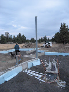
Aug 26  : High Mass Storage PEX tubing is gathered at the location of the solar hot water supply and return manifolds to be located in the Utility Room, as shown in the "Utility Room Solar Piping Layout" sketch, below.


Aug 27  : High Mass Storage PEX tubing is covered with 3" of sand for protection against UV degradation and possible damage from construction foot traffic while the circuits are pressure tested for leaks, below.


Aug 29 :  Lotte and I arrive for several days, meet with Todd, the building inspector, and also meet with some suppliers to inspect and approve the use of a couple of salvaged solar collectors to be included in the solar array, plus locate a source of sand only a few  miles away that is being excavated from a construction site, which we decide to use to complete the high mass storage area.


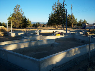
A "Jumping Jack" compactor sits idle awaiting the scheduled delivery, on Tuesday morning, Aug 31st, of over 121 tons ( 7 dump trucks full) of salvaged sand from a nearby construction site.


Wednesday, August 25, 2010

Aug 23-25: High Mass Storage Tubing

After the bottom of the high mass storage area is insulated, a 6" layer of soil from the excavation pile is compacted on top of the insulation layer.  A welded wire mesh is placed over the compacted soil to create an even distribution of heat and provide a matrix for attaching the heat transfer tubing. 

 Aug 23: Compaction over insulation completed, below.

Aug 24: Welded wire mesh installed and PEX tubing installation begins.  All tubing circuits will start and end at manifolds located in the Utility Room.  A mock-up of the manifold location with the first circuit in place is shown in the photo, below.
High Mass Storage Tubing Layout

The drawing above shows the precise layout of each of ten 300' long circuits of 1/2" diameter PEX tubing, which will deliver heat from the solar collector array to the high mass storage area.  The photo below shows the first circuit in place, which is attached to a wire mesh and corresponds to the circuit appearing in the lower right-hand corner on the drawing.


Aug 25: PEX tubing installation completed, below.  The ambient temperature reached 110 F today!

Saturday, August 21, 2010

Aug 20: High Mass Storage Insulation (to be continued)

Unfortunately around 2pm today, the portable job site table saw that Todd was using to rip the rigid insulation suddenly stopped working, so the high mass storage insulation was not finished today as planned, but would need to be completed tomorrow,  to keep to the tight schedule. 


Todd is in on a tailgate meeting with an electrician to quote the job.


Sonny is Todd's smart devoted Australian Shepherd that watches the tools.  He's a good dog, but no one messes with Sonny's tools unless Todd says it's OK.  


Thursday, August 19, 2010

Aug 19: Stem Wall Poured, Forms Stripped & High Mass Storage Insulation Installed

The stem wall was successfully poured and stripped of formwork.   Work started immediately on preparing the high mass storage area today.  2" of Dow Blueboard extruded polystyrene rigid insulation is shown being placed on top of bedrock in the following photos  to insulate the storage area.  Footing and stem wall will also be insulated in a similar manner.  

I arrived from San Francisco for a site visit today to review details with Todd and meet with Terry, our concrete subcontractor, to review and approve the most effective strategy for minimizing and controlling cracking in the honed and stained concrete slab, which will be our finished floor.  


The stem wall was poured with a 20% fly ash content.


Two inches of soil from our excavation pile is sprayed with water and compacted on top of bedrock to create a smooth and stable surface for the placement of insulation.  The compaction process is shown in the video, below.


Tuesday, August 17, 2010

Aug 16: Prep for Stem Wall Pour

These photos show the placement of rebar around the main cable truss post.  The stem wall forms jog around the post and rebar for good concrete coverage of the assembly. 


The following photos show details of the rebar assembly that will tie the base of the main cable truss into the concrete footing and stem wall for maximum strength for an important structural connection.

At the end of a hot day, which Todd said reached 100 deg F, tube steel posts stand braced, steel rebar is in place, and stem wall forms are up and baking in the high desert sun ready to receive the cool early morning pour of concrete.


Saturday, August 14, 2010

Aug 13: Main Cable Truss Post

The main cable truss post will be 13 feet (4 m) long and is a tube steel structural column 6" x 6" x 1/2" thick, which weighs 600 pounds.  It's a key element for anchoring the cable truss, which spans 33 feet (10 m) and will support a vaulted roof.  The orientation of the post is critical to avoid eccentric loading.  The location and orientation for the post is shown on the drawing, below. The post is bolted with epoxy to the footing and embedded in concrete in the stem wall with vertical rebar and stirrups.

Aug 12: Stem Wall Goes UP


Stem wall formwork positioned around Dining Room posts.


View looking NW from Guest Bedroom wing.


8 PVC sleeves shown in-place to penetrate an interior stem wall to allow 1/2" dia. PEX tubing to pass through, which will deliver solar heat to a proposed high mass sand storage zone located directly beneath the slab.


View of proposed Dining Room looking NW.


A segmented foundation follows a curve along the east side of the Guest Bedroom wing. 


Formwork jogs to create a wider stem wall to support a double width concrete block wall with insulation in between, for the corner of the Living Room behind the wood stove. 


View of Mt. Jefferson from the Living Room.


Wednesday, August 11, 2010

Aug 6: Footer is Down!


Photo from Todd showing the 3x3 x1/4" tube steel posts, with 12"x12"x1/2" steel base plates that have been welded onto the posts.  The plates are bolted in-place 12" into the bedrock at the corners of the Dining Room over a dry-pack concrete mix, which will be embedded in the footing. 


Dining Room tube steel posts in place, braced, and ready for the footing to be poured.


On a job site visit on Aug 3, I inspected the corners of the Dining Room, which shows the exposed bedrock at one corner.


Todd sent me a text message with the last photo of the day, which said, "Footer is down."  


What's that?  You haven't seen any wildlife yet? Well, if you haven't seen any, you can rest assured that it sees you.